
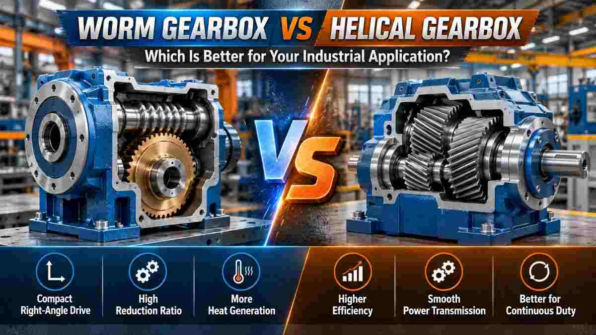
Choosing between a worm gearbox and a helical gearbox is an important decision for industrial machinery that requires controlled speed, reliable torque transmission, and efficient operation.
Both gearbox designs reduce rotational speed and increase output torque, but they achieve this through different gear arrangements. These differences influence efficiency, heat generation, shaft configuration, maintenance requirements, and operating costs.
The main difference between a worm gearbox vs helical gearbox is how the gears transmit power. Worm gearboxes use a screw-like worm and a mating worm wheel, making them useful for compact right-angle drives and high reduction ratios. Helical gearboxes use angled gear teeth that engage progressively, making them particularly suitable for efficient and smooth power transmission.
Neither design is automatically better for every application. The correct choice depends on operating speed, output torque, duty cycle, available installation space, and overall project requirements.
This guide compares worm and helical gearboxes to help engineers, industrial buyers, and maintenance teams make an informed selection.
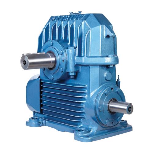
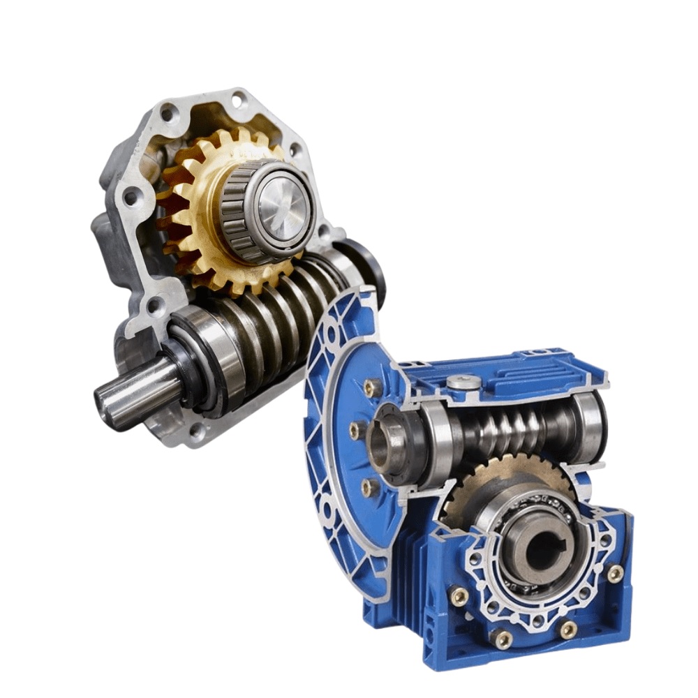
A worm gearbox is a mechanical speed reduction system consisting of a screw-shaped worm and a mating worm wheel.
As the worm rotates, its threads engage with the teeth of the worm wheel, causing the output shaft to rotate at a reduced speed.
Worm gearboxes commonly transmit power between nonparallel, nonintersecting shafts arranged at approximately 90 degrees.
The design can achieve substantial speed reduction in a single gear stage, making it useful where a compact arrangement and a high reduction ratio are required.
A worm reduction gearbox can be considered for applications such as:
However, worm gearboxes generate sliding friction between the meshing surfaces, which can increase heat generation and reduce mechanical efficiency compared with many helical gearbox designs.
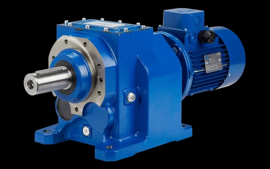
A helical gearbox uses gears with teeth cut at an angle to the gear axis.
Unlike straight-cut gears that engage more abruptly, helical gear teeth enter contact progressively. This engagement helps distribute loads and supports relatively smooth power transmission.
Helical gearbox arrangements may use parallel-shaft, inline, or other configurations depending on the gearbox design.
Because helical gearing generally experiences lower sliding losses than worm gearing, it is commonly selected for applications requiring high efficiency and continuous operation.
A helical gearbox can be suitable for:
Helical gearboxes must still be selected according to their rated torque, speed, mounting arrangement, lubrication requirements, and thermal capacity.
The most significant differences are their gear geometry, power transmission efficiency, shaft arrangement, and operating characteristics.
| Feature | Worm Gearbox | Helical Gearbox |
|---|---|---|
| Gear Design | Screw-like worm and mating worm wheel | Gears with angled teeth |
| Typical Shaft Arrangement | Right-angle, nonintersecting shafts | Inline or parallel shafts in common configurations |
| Power Transmission | Significant sliding contact | Predominantly rolling contact with some sliding |
| Efficiency | Often lower, especially at high ratios | Generally higher |
| Speed Reduction | High ratios possible in one stage | High overall ratios generally require multiple stages |
| Heat Generation | Often higher for comparable transmitted power | Generally lower for comparable conditions |
| Noise | Can operate quietly at suitable speeds and loads | Gradual tooth engagement supports smooth, quiet operation |
| Backdriving | May resist backdriving under certain conditions | Generally backdrivable |
| Continuous Operation | Possible within mechanical and thermal ratings | Commonly preferred for efficient continuous duty |
| Maintenance | Requires appropriate lubrication and thermal monitoring | Requires appropriate lubrication and mechanical inspection |
| Cost | May offer a compact, economical option | May offer lower energy costs over long duty cycles |
These are general comparisons. Actual gearbox performance depends on the manufacturer's design, materials, reduction ratio, input speed, lubrication, and operating conditions.
Helical gearboxes are generally more efficient than conventional worm gearboxes because their gear teeth transmit power with a larger rolling-contact component and lower sliding losses.
Worm gearboxes experience significant sliding contact between the worm and worm wheel. This generates friction and converts part of the input power into heat.
Typical efficiency characteristics vary with design:
A complete gearbox may have lower efficiency than an individual gear stage because bearings, seals, and additional stages introduce mechanical losses.
For machinery that operates continuously, a relatively small efficiency difference can significantly affect long-term electricity consumption.
Consider an illustrative industrial application requiring 5 kW of mechanical output power.
Assume two gearbox options have the following overall efficiencies:
The approximate input power required by each gearbox is calculated using:
Input Power = Required Output Power / Gearbox Efficiency
For the worm gearbox:
5 / 0.75 = 6.67 kW
For the helical gearbox:
5 / 0.95 = 5.26 kW
The difference is approximately 1.40 kW of input power under these assumed conditions.
If the machine operates for 3,000 hours annually, this represents approximately 4,211 kWh of energy difference at the gearbox input.
Actual savings depend on the efficiency of the selected products, loading conditions, operating hours, and drive system. These figures are illustrative, not specifications for Agni Engineering products.
Both worm and helical gearboxes can provide high output torque when correctly designed and sized.
A gearbox increases torque by reducing rotational speed, with the actual output also influenced by transmission efficiency.
The approximate relationship is:
Output Torque (Nm) = 9550 × Output Power (kW) / Output Speed (RPM)
For example, if a gearbox delivers 5 kW of output power at 100 RPM:
Output Torque = 9550 × 5 / 100
Output Torque = 477.5 Nm
However, the calculated torque must still fall within the gearbox's allowable mechanical and thermal ratings.
Worm gearboxes may provide substantial speed reduction in a compact single-stage design, while multistage helical gearboxes can transmit high torque efficiently across demanding industrial applications.
The correct gearbox must be selected according to the required output torque, shock loading, service factor, and duty cycle rather than gear type alone.
Worm gearboxes can achieve relatively high reduction ratios in a single gear stage.
This is one of their important design advantages when space is limited.
For example, a suitable worm gear arrangement may provide a reduction ratio of 40:1 in one stage.
A typical helical gearbox may require multiple stages to achieve an equivalent overall reduction ratio.
However, a higher reduction ratio in a worm gearbox can also increase sliding losses and reduce efficiency.
The reduction ratio should be selected based on the required output speed and actual machine operating conditions.
The gearbox reduction ratio can be estimated using:
Reduction Ratio = Input Speed / Required Output Speed
For example, if a motor operates at 1,500 RPM and the required output speed is 50 RPM:
Reduction Ratio = 1500 / 50
Required Reduction Ratio = 30:1
Both worm and multistage helical gearbox arrangements may be capable of providing this reduction, depending on the selected model.
Engineers should also verify the required output torque and operating efficiency before choosing the final gearbox.
Worm gearboxes commonly generate more heat because of the substantial sliding contact between the worm and worm wheel.
The resulting friction causes part of the input energy to be lost as heat.
Helical gearboxes generally experience lower frictional losses for comparable operating conditions.
Heat generation depends on:
When selecting a worm gearbox for continuous operation, thermal capacity should be evaluated alongside mechanical torque capacity.
An otherwise correctly sized gearbox may still be unsuitable if it cannot dissipate the heat generated during the intended duty cycle.
Some worm gearbox designs resist reverse motion because of their gear geometry and frictional characteristics.
This behavior is sometimes described as self-locking.
However, not all worm gearboxes are self-locking, and self-locking behavior may change with wear, lubrication, vibration, temperature, and operating conditions.
A worm gearbox must not automatically be treated as a safety brake.
Applications involving suspended loads, lifting equipment, or personnel safety may require an independently rated braking or load-holding system.
Helical gearboxes are generally backdrivable and are not intended to prevent reverse rotation without additional equipment.
Both gearbox types require appropriate lubrication, inspection, and maintenance.
Worm gearboxes often require particular attention to lubricant compatibility and temperature because of their sliding contact characteristics.
Helical gearboxes also require proper oil selection and monitoring of bearings, gear teeth, seals, and alignment.
Important maintenance checks include:
Maintenance intervals should follow the gearbox manufacturer's instructions and the actual operating conditions.
Neither design is maintenance-free, and one cannot be declared universally longer-lasting without comparing specific models and applications.
Helical gearboxes are frequently preferred for continuous industrial operation because of their generally high efficiency and comparatively lower heat generation.
They are commonly used in equipment operating for extended periods, including conveyors, mixers, production machinery, and processing systems.
Worm gearboxes can also support continuous operation when their mechanical load and thermal ratings are suitable for the duty cycle.
The final decision should consider:
For a machine running continuously throughout the year, gearbox efficiency can be an important factor in total operating cost.
A worm reduction gearbox may be a practical option when the machine requires a compact right-angle drive with substantial speed reduction.
It may be worth considering when:
Applications can include packaging systems, smaller conveyors, valve actuation equipment, and selected positioning mechanisms.
However, actual suitability depends on the required torque, input speed, duty cycle, and gearbox specifications.
A helical gearbox is often suitable when the application prioritizes efficient power transmission, continuous operation, and smooth running.
It may be preferred when:
Helical gearboxes are commonly used in industrial conveyors, mixers, material-handling equipment, textile machinery, and manufacturing production lines.
Selection should be based on specific gearbox ratings rather than assuming every helical gearbox can handle every heavy-duty application.
Conveyor systems can use either worm or helical gearboxes depending on their layout, operating hours, loading characteristics, and speed requirements.
A worm gearbox may be suitable for a compact conveyor requiring a right-angle drive and moderate operating duty.
A helical gearbox may be more suitable for a heavily used conveyor where high efficiency and continuous power transmission are important.
Before making a decision, determine:
The selected gearbox should meet both the mechanical requirements and the expected duty cycle.
Before purchasing a gearbox, industrial buyers should prepare a clear technical specification.
Important details include:
Agni Engineering offers industrial gearbox solutions, including worm reduction and helical gearbox designs for different power transmission applications.
Comparing the actual operating requirements with the available gearbox specifications helps reduce the risk of incorrect selection.
Generally, yes. Helical gearboxes typically have lower gear-mesh losses than conventional worm gearboxes. Actual efficiency depends on the gearbox design, reduction ratio, speed, load, and lubrication.
Both designs can provide high torque when appropriately sized. The correct choice depends on output torque requirements, reduction ratio, duty cycle, and the gearbox's mechanical and thermal ratings.
A worm gearbox may have a lower initial cost for certain compact applications, but the total cost also depends on efficiency, electricity consumption, maintenance, and service life.
Yes, provided the gearbox is rated for the intended load, speed, ambient conditions, and continuous-duty thermal requirements.
Standard parallel-shaft helical gearboxes do not provide a right-angle output. However, gearbox designs combining helical and bevel gearing can deliver power through a 90-degree arrangement.
No. Self-locking depends on the gear geometry, friction, lubrication, and operating conditions. Even a potentially self-locking worm gearbox should not be used as a substitute for a safety-rated brake.
Helical gearboxes are often preferred for long operating hours because of their high efficiency. However, a properly rated worm gearbox can also operate continuously when its thermal and mechanical limits are respected.
The choice between a worm gearbox and a helical gearbox should be based on the machinery's operational requirements rather than general assumptions about performance.
A worm gearbox can be suitable when compact right-angle power transmission and high reduction ratios are priorities.
A helical gearbox may be the better option when continuous operation, efficient power transmission, and lower energy losses are more important.
Agni Engineering provides worm reduction gearboxes, helical gearboxes, and other industrial power transmission products for different machinery requirements.
Before selecting a gearbox, evaluate the required torque, speed reduction, duty cycle, mounting configuration, operating environment, and long-term running cost. Choosing according to these factors can help improve equipment performance and reliability.
Industrial machinery depends on reliable...
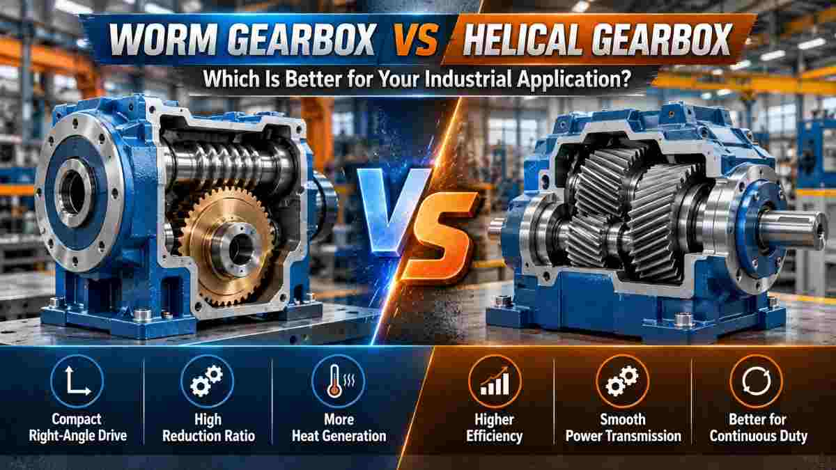
Choosing between a worm gearbox and a he...
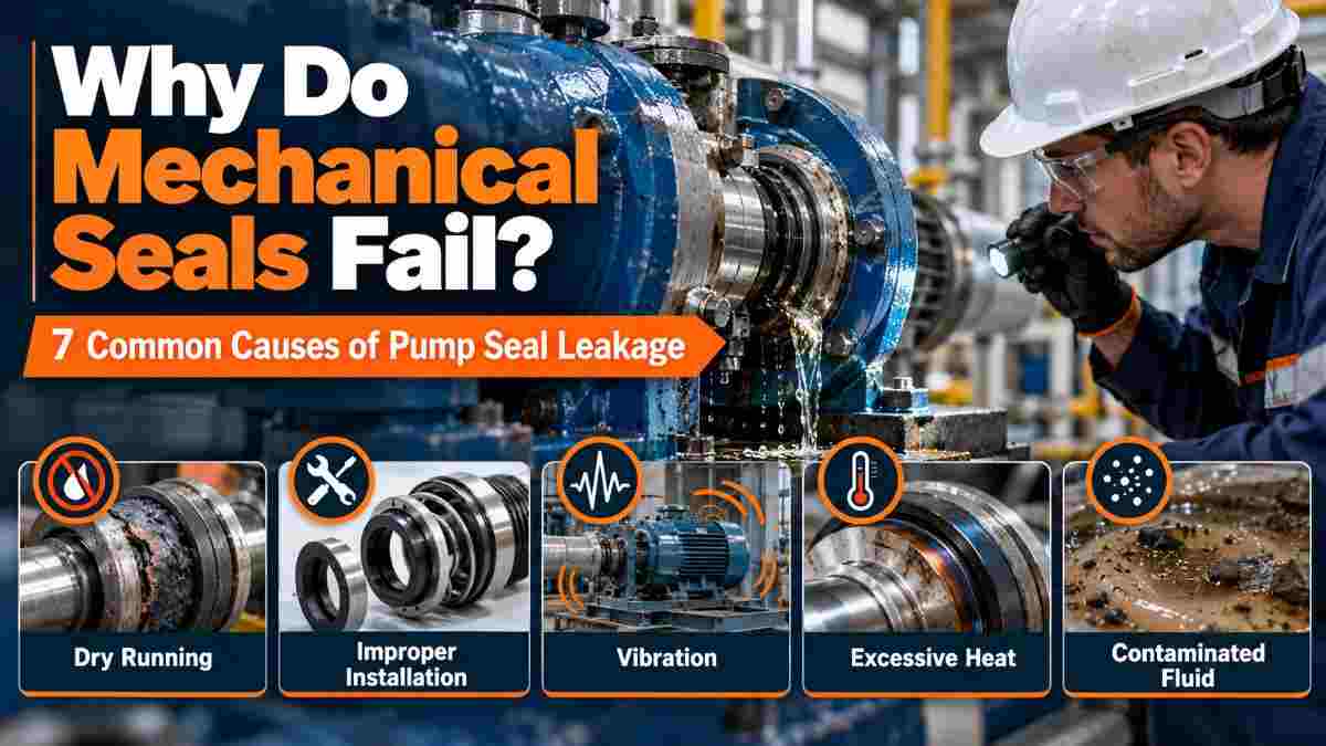
Mechanical seals are essential component...
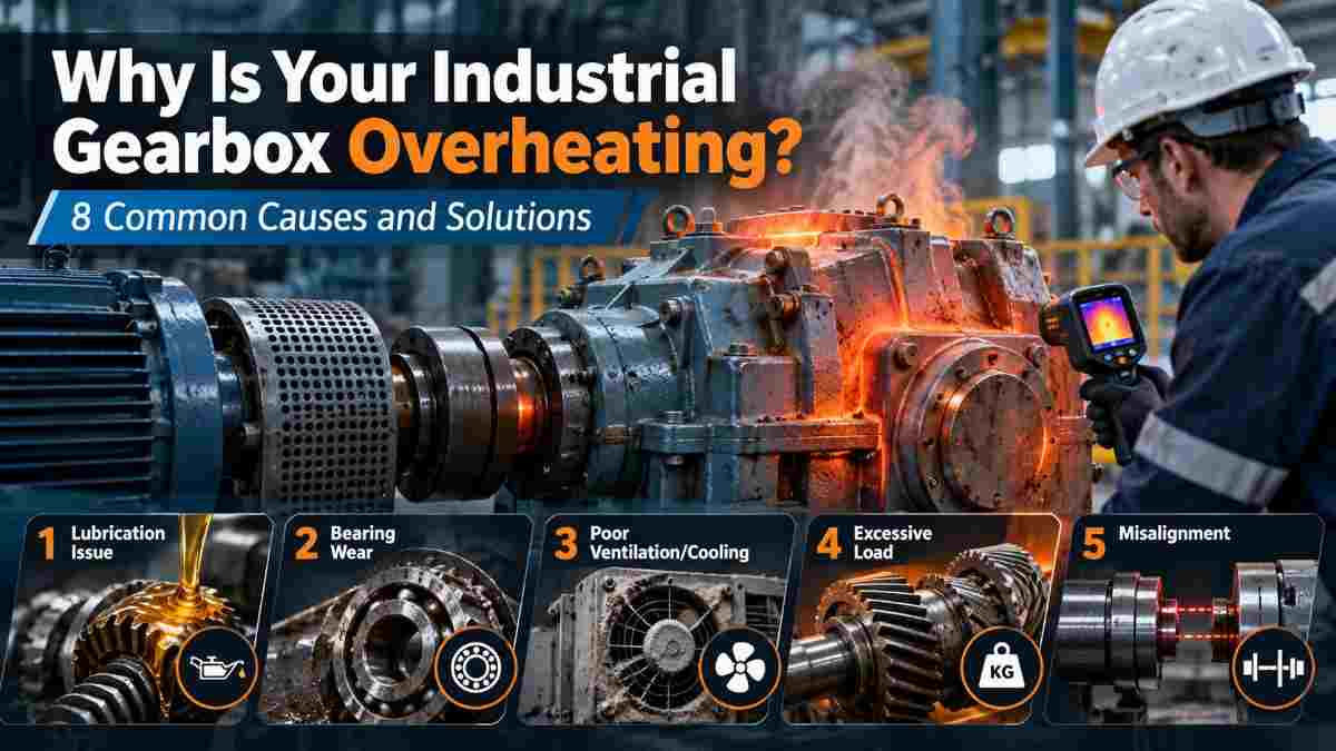
An industrial gearbox naturally generate...
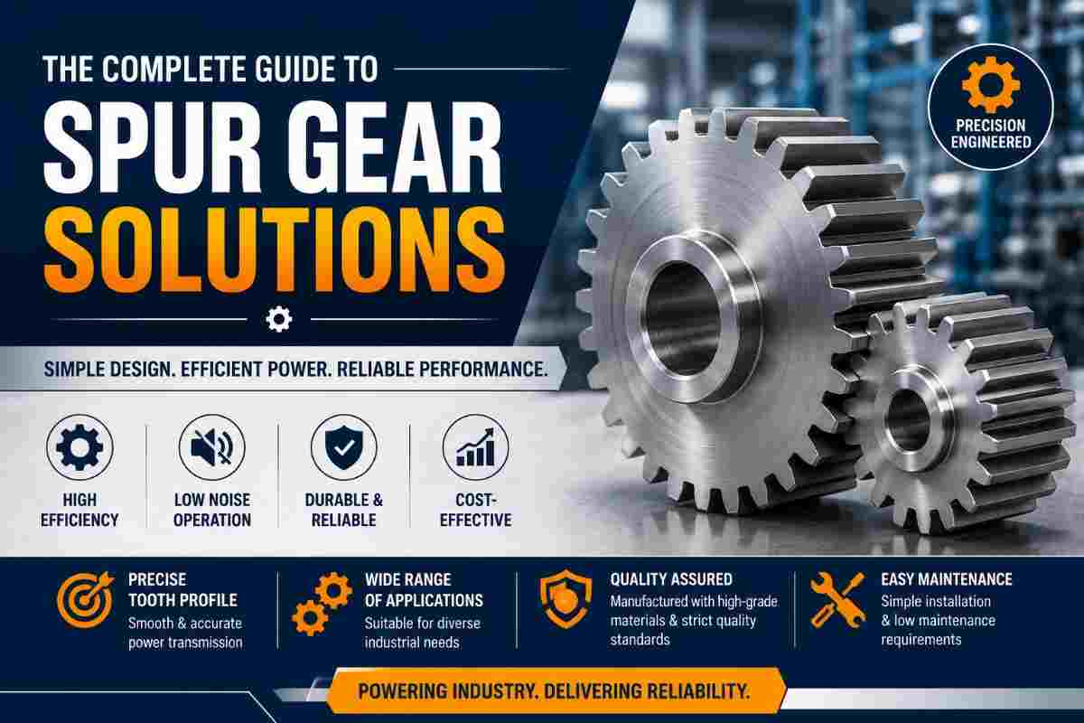
A spur gear is a mechanical gear with st...
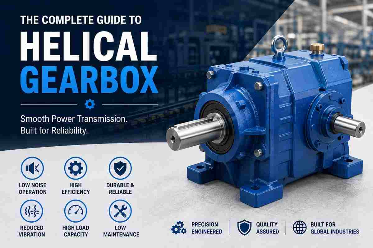
A helical gearbox is a mechanical power ...
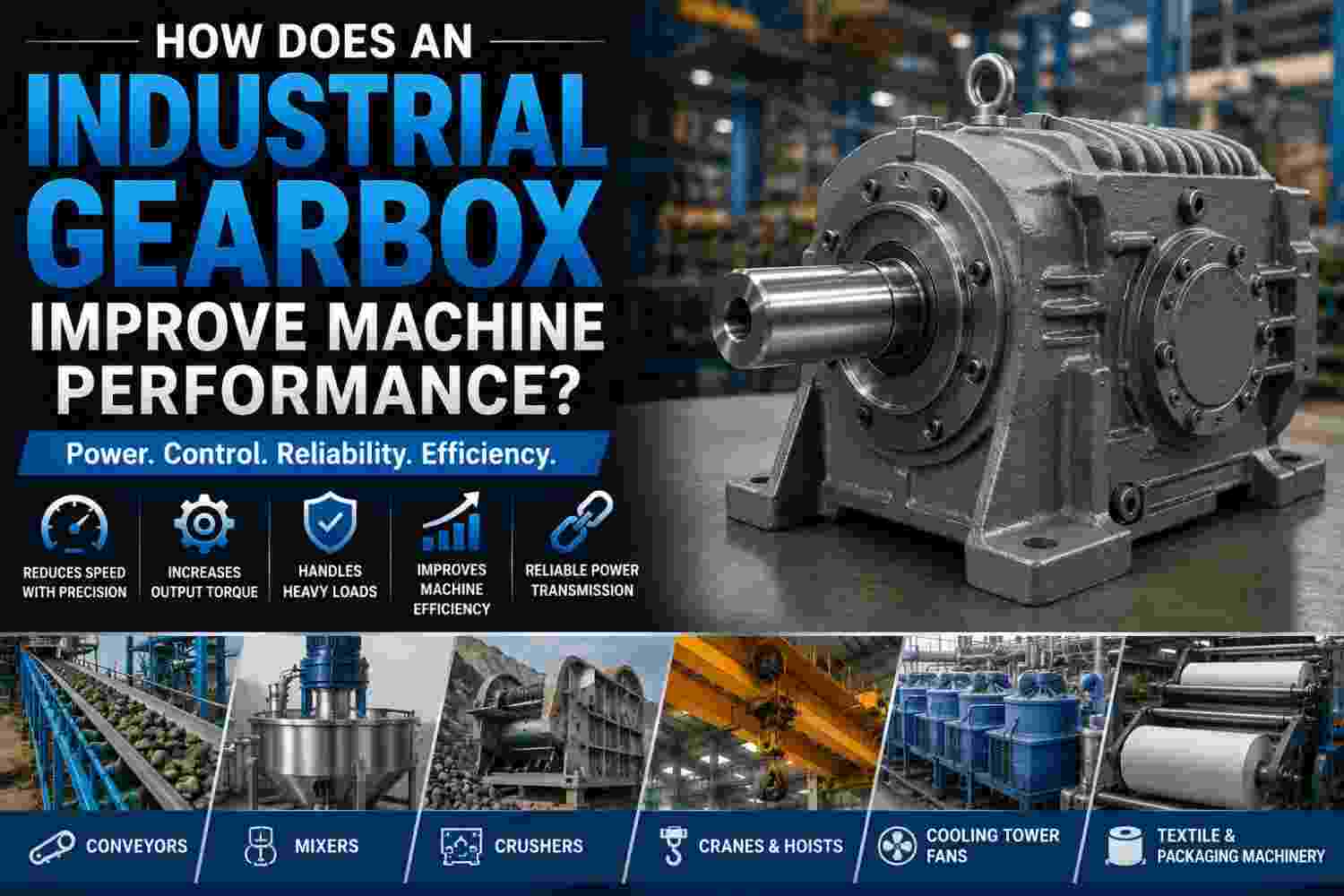
An industrial gearbox improves machine p...
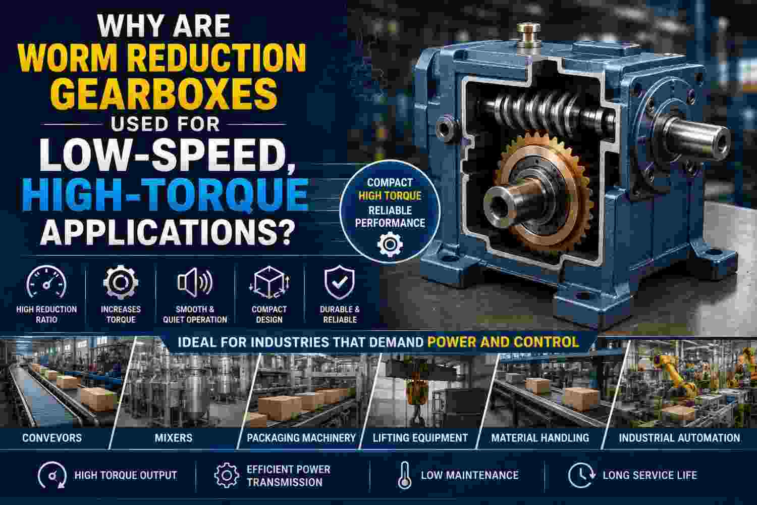
Worm reduction gearboxes are used for lo...
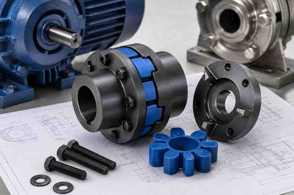
Selecting the correct N-Eupex coupling i...
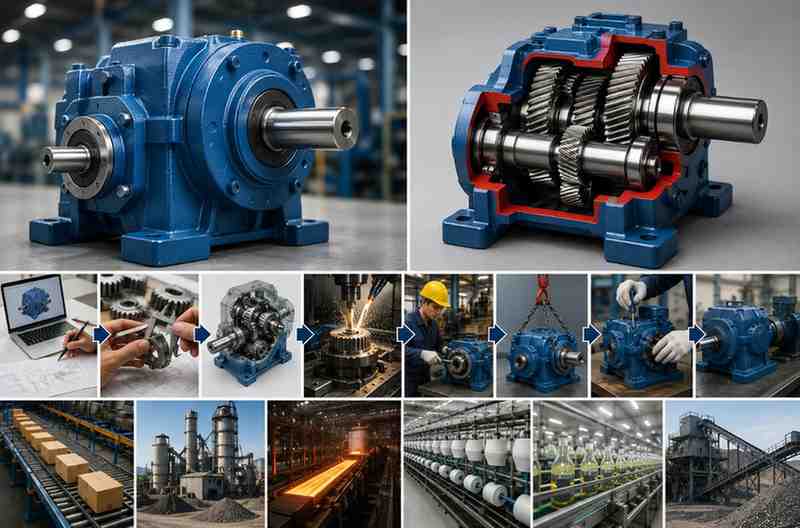
Choosing the right helical gearbox is on...
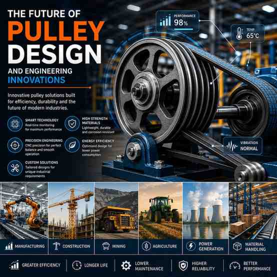
For centuries, pulleys have been one of ...
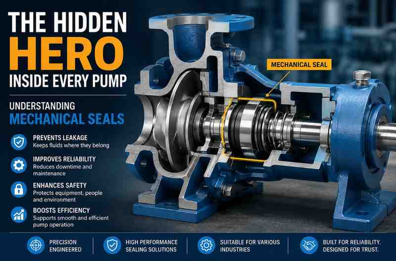
When people think about industrial pumps...
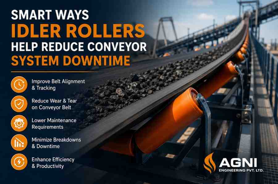
In industries where material handling is...
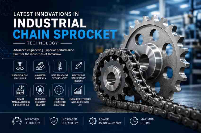
In today’s fast-moving industrial envi...
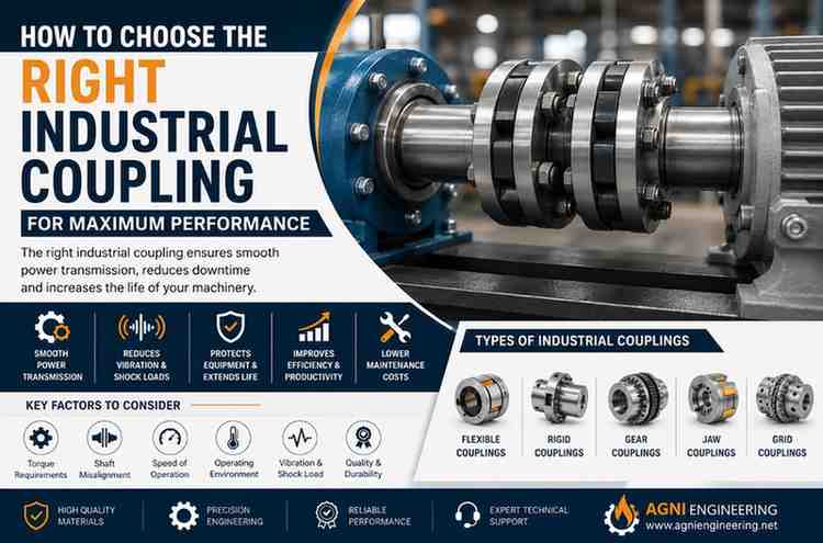
In any industrial setup, even the smalle...
Industrial operations today are becoming...
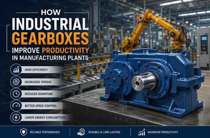
In modern manufacturing plants, efficien...
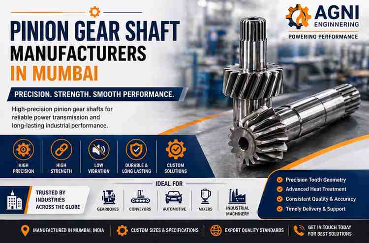
In industrial machinery, every movement ...
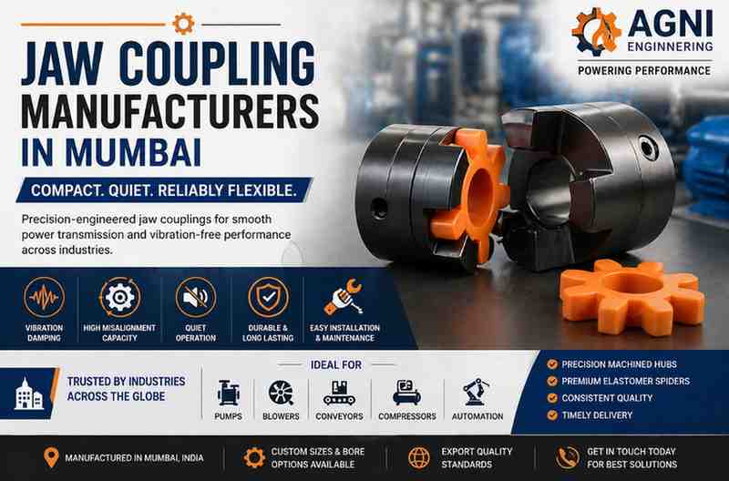
In modern industrial machinery, smooth p...
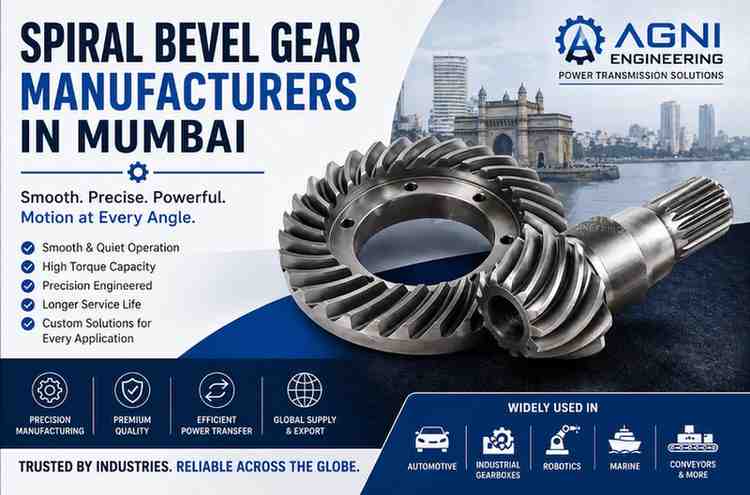
In modern industries, machines rarely wo...
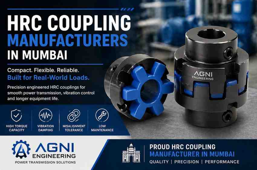
In industrial machinery, smooth power tr...

Machines depend on smooth and steady mot...

In any industrial system, smooth power t...

In many industrial machines, smooth moti...
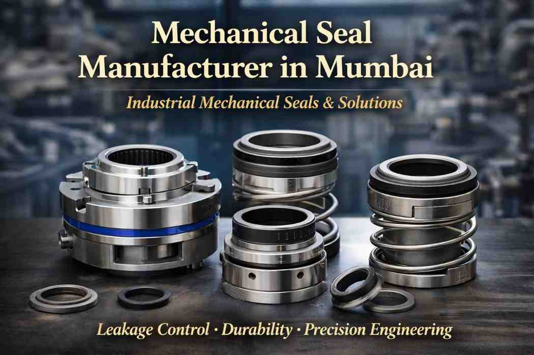
Industrial machines operate under pressu...
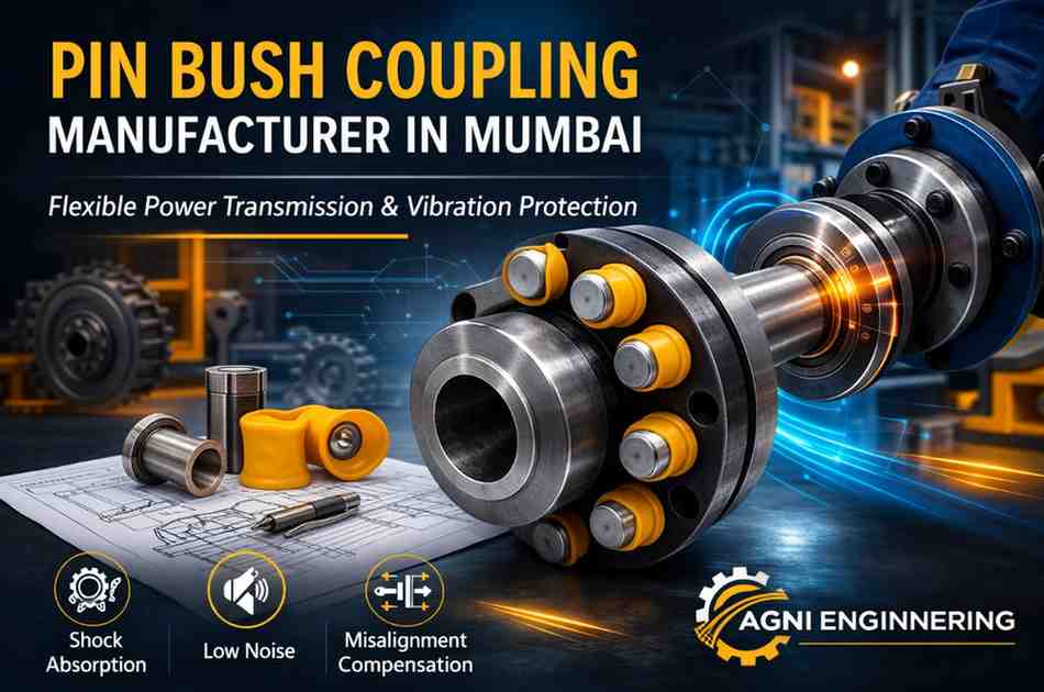
In many industrial machines, vibration, ...
In every conveyor system, rollers play a...
In modern machines, power does not alway...
Some mechanical components earn their re...
Power transmission begins with a single,...
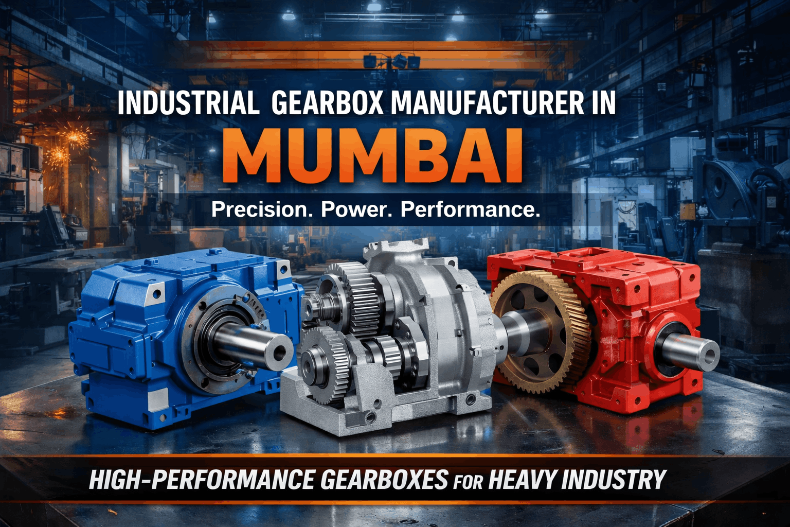
Behind every smooth-running industrial m...

In heavy-duty mechanical systems, power ...

In mechanical systems, reliability often...

In industrial environments where machine...
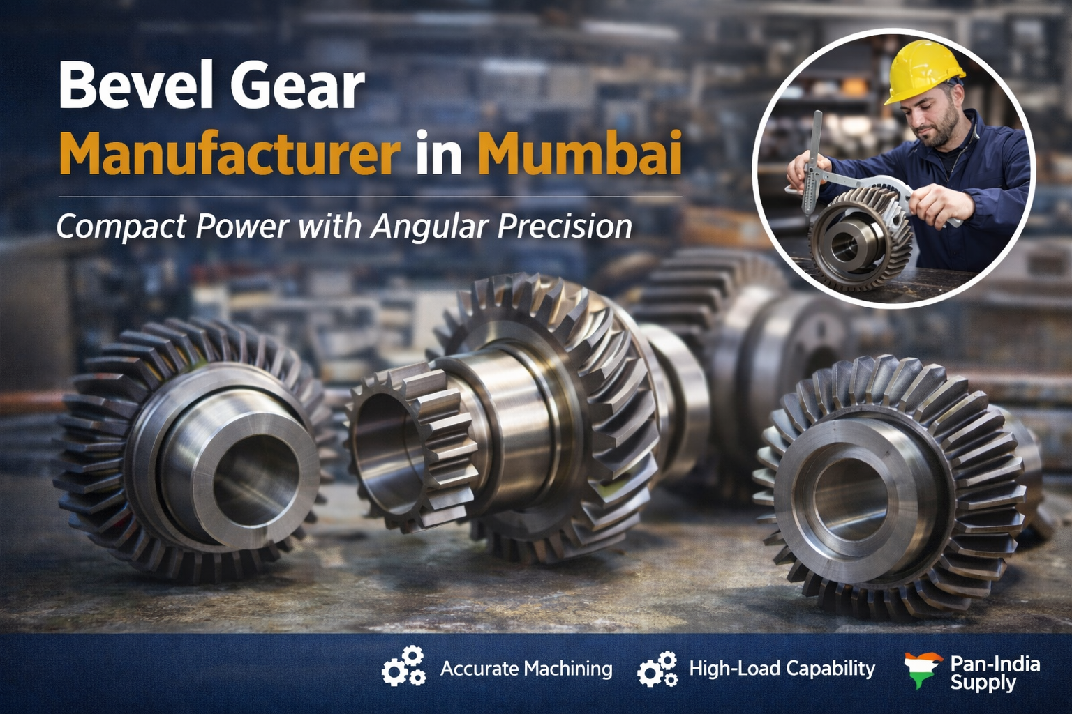
Machines that rely on angular power tran...
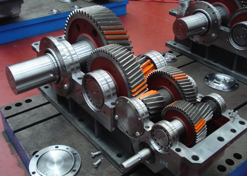
Modern industries run on reliability. Wh...
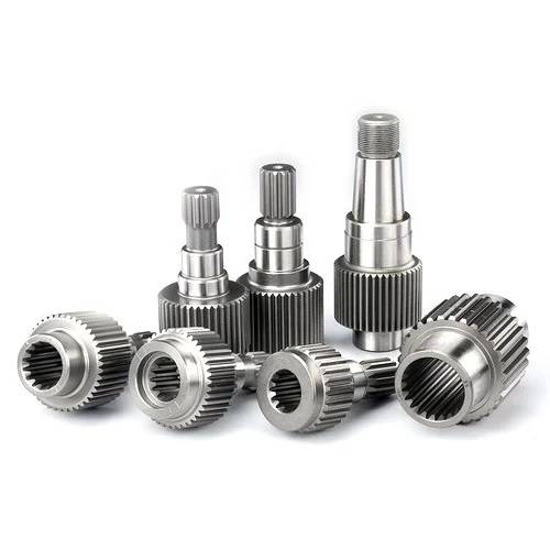
The Pinion Gear Shaft Manufacturers in M...
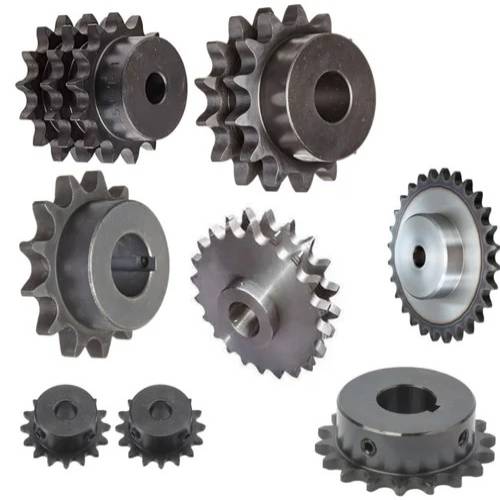
...
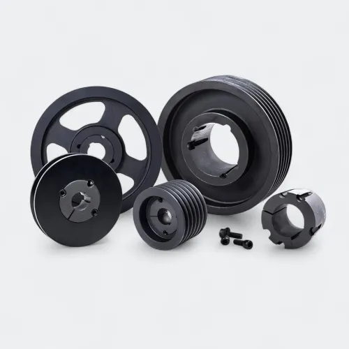
When machines need dependable power, smo...
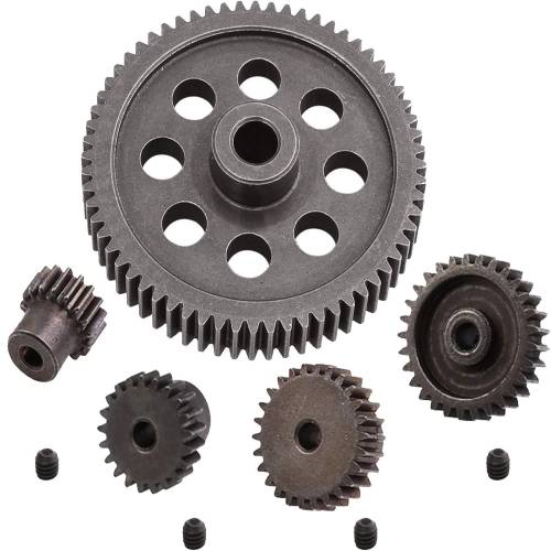
The Spur Gear Manufacturers in Mumbai ar...
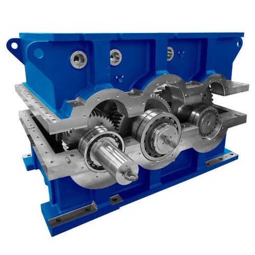
The Gearbox Manufacturers in Mumbai play...
When precision meets performance, indust...
In the modern industrial world, precisio...
In today’s fast-paced industrial world...
When it comes to advanced power transmis...
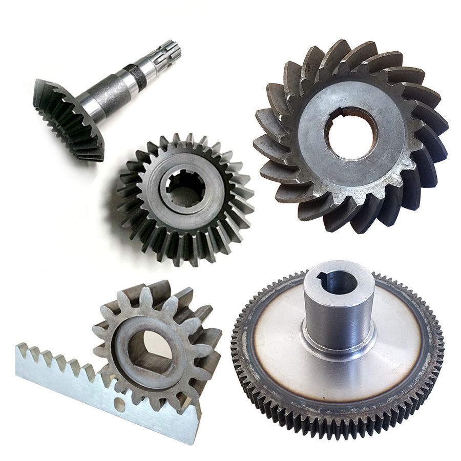
In the world of modern engineering, Indu...
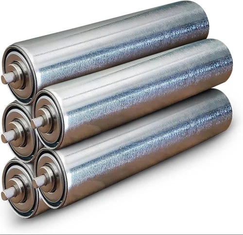
In the world of material handling and co...
